
AWJ Cutting Process Quality Modeling and Optimization Based on Footprint Angle
Abstract
Highlights:
What are the main findings?
What is the implication of the main finding?
Abstract:
Various materials may be machined using the abrasive water jet (AWJ) cutting method. Many control factors, such as abrasive flow, operating pressure, and traverse speed, influence the efficiency and surface quality of AWJ-cut components. The common distinguishing factor of process efficiency and quality is the angle of machining footprints (striation angle). This paper presents research results on the control parameters as a method of influencing the striation angle through the angle level of machining footprints to achieve high efficiency and quality, for example, the high-impact and abrasive-resistant steel. This will enable quality control of the AWJ cutting process by continuously measuring the jet deflection angle in an online mode and adjusting these parameters in real-time to maintain high efficiency and the required surface quality. The particular interest in utilizing this basis is the possibility of setting cutting parameters for new materials not included in the implemented model of the AWJ cutting machine.
Article type: Research Article
Keywords: abrasive water jet, machining efficiency, machining quality, modeling, prediction
License: © 2025 by the authors. CC BY 4.0 Licensee MDPI, Basel, Switzerland. This article is an open access article distributed under the terms and conditions of the Creative Commons Attribution (CC BY) license (https://creativecommons.org/licenses/by/4.0/).
Article links: DOI: 10.3390/ma18245548 | PubMed: 41470321 | PMC: PMC12735301
Relevance: Moderate: mentioned 3+ times in text
Full text: PDF (3.8 MB)
1. Introduction
A high-velocity water jet, combined with abrasive grains, is used in the unconventional machining technique known as AWJ machining to treat materials. It is a versatile cold-cutting technology that uses a high-velocity waterjet (typically 600–900 m/s) loaded with hard abrasive particles (usually garnet) to erode virtually any engineering material without inducing thermal damage or significant mechanical stresses. It is renowned for its capacity to machine intricate forms without causing thermal damage. High-pressure AWJ processing has recently successfully competed with traditional methods of material separation. The opportunity to cut intricate shapes [ref. 1,ref. 2] a diverse array of materials [ref. 3,ref. 4], including those that are difficult to machine [ref. 5,ref. 6], and the potential to carry out the process in harsh environments [ref. 7,ref. 8] (failure by fire or explosion, underwater operation, etc.) are the main reasons for this cutting technology’s versatility.
The application of this process is predominantly attractive for difficult-to-machine materials such as hardened steels [ref. 5,ref. 9,ref. 10], titanium alloys [ref. 6,ref. 11,ref. 12], nickel superalloys, and even tungsten alloys [ref. 13] or metal-matrix and polymer-matrix composites [ref. 14,ref. 15], ceramics [ref. 16,ref. 17], and ultra-high-strength steels, which are prone to cracking, heat-affected zones, or tool wear when processed by conventional methods. In comparison with common separation methods, this innovative production technology is characterized by a greater number of process parameters.
The material removal mechanism in AWJ combines three main erosion modes: micro-cutting, plastic deformation/plowing, and intergranular cracking/brittle fracture, whose relative contribution depends on the target material’s ductility, hardness, and fracture toughness [ref. 18,ref. 19,ref. 20]. In the upper zone of the kerf at shallow depth, the AWJ retains most of its kinetic energy and removes material primarily by microcutting, creating relatively smooth surfaces. As the jet penetrates deeper, it loses cohesion and kinetic energy due to viscous drag, abrasive particle fragmentation, and jet dispersion by the air. This leads to a gradual transition to deformational wear and fatigue-dominated erosion at greater depths, which manifests itself macroscopically as distinct curved striations (machining marks) and increasing surface roughness with depth [ref. 21,ref. 22,ref. 23].
Pressure increases jet velocity and thus kinetic energy of both water and abrasives, causing a higher material removal rate and deeper penetration, but also faster focusing-tube wear and higher energy consumption [ref. 24,ref. 25].
A higher abrasive mass flow rate supplies more cutting edges per unit time and causes increased depth of cut and reduced striation (footprint) angle up to an optimum. Beyond this point, further increases in abrasive flow yield a drop in returns and may even deteriorate surface quality due to particle interference and jet destabilization [ref. 26,ref. 27,ref. 28].
Traverse speed directly controls specific energy input per unit length. Low traverse speeds produce smooth, almost striation-free surfaces (Q5–Q4 quality classes [ref. 29]) but low productivity. High speeds dramatically increase the striation (footprint) angle, surface roughness, and kerf taper while reducing the depth of cut [ref. 30,ref. 31,ref. 32].
Therefore, modeling and a contemporary optimization approach are necessary to achieve excellent results [ref. 32]. Different statistical and mathematical techniques [ref. 33], metaheuristic approaches [ref. 34,ref. 35], methods that aid in decision-making [ref. 27,ref. 36,ref. 37], and even AI methods [ref. 38,ref. 39,ref. 40] and finite element methodology [ref. 41] were employed for this aim.
Dahil et al. [ref. 42] presented the most advantageous cutting method for high hardness, high strength, and superior toughness of Hardox 500 steel cutting. The authors presented the comparison of cuts by plasma, laser, wire erosion, and abrasive water jet (AWJ) methods. Based on microstructure photos of the cut surface made by different methods; the effects on the material’s metallurgical structure were compared.
Surfaces cut by the AWJ, because no thermal change did not occur on the jet contact area with the material, did not have any microstructure change or hardness differences, as in the other tested cutting. The cutting performance of multipass abrasive waterjet (AWJ) machining on Hardox steel was presented by Dekster et al. [ref. 10]. Research has shown that the right cutting parameters can result in superior performance with multipass cutting compared to single-pass cutting. It was shown that multipass cutting is rather efficient in increasing the depth of penetration and reducing the kerf taper angle, as it achieves 3 to 9 times higher depths.
Krenicky et al. [ref. 43] investigated how important control factors affected the surface quality of abrasive water jet (AWJ) cuts produced in Hardox (TM). Unfortunately, the equations were only created for measurements in one profile—the Ra and Rz roughness parameters—after the regression technique was applied to the collected data. To check the relations between Ra and Rz and the cutting parameters of pressure, traverse speed, and abrasive mass flow rate, regression equations were created. Regression equations describing correlations between the declination angle in the kerf as the independent variable, and the authors also provided either the Ra or the Rz parameters as dependent variables. Surface quality and cutting efficiency may be predicted using these models.
The surface quality of AWJ-cut parts is crucial in determining the cut components’ functional performance [ref. 44]. In this article, the impact of the three most significant control parameters—traverse speed, operating pressure, and abrasive flow—on one easy-to-observe factor, the jet deflection angle, was examined. It can be used to assess the treatment’s efficiency and quality in real time.
To determine the titanium surface profiles eroded by an abrasive waterjet (AWJ), Yuan Yemin et al. [ref. 45] created a surface profile evolution model that suppressed the AWJ’s eroding capacity and considered the jet’s directional deflection. Nonetheless, the findings showed that the roughness contours described by the surface development model agreed with the actual contours with a significant error of 11.4%.
Wala et al. [ref. 46] suggested comparing the chosen signal features of the cutting factors, which control the process course, and the parameters associated with the machined surface produced. The feed force recorded by the cutting process served as the basis for the AWJ deflection angle model.
Meanwhile, Brandstätter et al. [ref. 47] investigated the relationship between surface quality and the abrasive waterjet material disintegration parameters associated with machining marks. Materials with a wide range of hardness values were examined, such as aluminum, steel, and polyethylene plastic. The experiments were used to determine surface quality to assign a range of surface roughness parameters R-z and R-a when distinct machining marks cannot be recorded on the surface of specific materials with specific mechanical properties.
In the Lebar et al. paper [ref. 48], the possibility of using the thermovision camera or, for cutting transparent targets, an optical camera to examine the propagation of the AWJ cutting front was investigated. The characteristics of the cutting front can be extracted from the resulting photographs using digital image processing techniques, enabling process control.
The characteristic curved striations visible on AWJ-cut surfaces are a direct consequence of unsteady cutting front propagation and jet deflection toward the feed direction. The local striation (or footprint) angle δ (sometimes called the “declination” or “lag” angle) has been shown to correlate strongly with both instantaneous material removal capability and final surface roughness [ref. 43,ref. 49]. A low λ (≤10–15°) indicates stable, high-energy cutting conditions and typically corresponds to Ra < 3–5 µm on steels, whereas λ > 25–30° signals severe jet energy depletion and rough surfaces (Ra > 10–15 µm).
Despite extensive literature on empirical modeling of depth, roughness, and kerf taper [ref. 32,ref. 35,ref. 36], relatively few studies have systematically exploited the striation/footprint angle itself as a real-time diagnostic and control variable. Hashish [ref. 21] and later Hlaváček et al. [ref. 50] suggested that the instantaneous jet deflection angle can be optically monitored during cutting, offering a simple, non-contact method for adaptive control. Recent works using high-speed imaging and thermography [ref. 38,ref. 48] confirmed the feasibility of such approaches, yet robust quantitative models linking the three main parameters (pressure, abrasive flow rate, and traverse speed) directly to the measurable footprint angle λ are still scarce, especially for ultra-high-strength wear-resistant steels such as Hardox 500.
The present study addresses this gap by investigating the influence of pressure (350–400 MPa), abrasive mass flow rate (250–450 g/min), and traverse speed (100–300 mm/min) on the footprint (jet deflection) angle λ during AWJ cutting of 20 mm thick Hardox 500 steel. Second-order polynomial response models were developed for cutting depth, 3D surface roughness Sq, and—most importantly—the footprint angle λ. The practical objective is to demonstrate that online measurement of λ can serve as a single, easy-to-acquire indicator for simultaneous control of productivity and surface quality, even for new or inhomogeneous materials not covered by the machine’s built-in technological database.
Based on the above state-of-the-art analysis, it was observed that the surface quality of parts cut using the AWJ method, particularly the angle of the cutting marks (jet deflection angle), is crucial for determining the functionality of the cut parts.
This paper focuses on the most influential control parameters, such as feed rate, operating pressure, and abrasive mass flow rate, that affect the jet deflection angle. The objective is to determine the feasibility of online control of the AWJ cutting process by measuring the jet deflection angle. To achieve this, it was decided to establish the jet deflection angle based on the machining marks left behind. Further research will be planned to develop this method using optical methods and online digital image processing.
2. Materials and Methods
2.1. Cutting Material
In the research, Hardox 500 steel, characterized by an average hardness of 500 HBW, produced by the SSAB company (Stockholm, Sweden), was used. Hardox 500 maintains high toughness despite its high hardness, which is a key differentiator from conventional wear steels. The significant properties of Hardox 500 were presented in Table 1.
Table 1: Hardox 500 mechanical and physical properties.
| Property | Value |
|---|---|
| Hardness | ~470–530 HBW (Brinell) |
| Yield Strength | ≥1000 MPa |
| Tensile Strength | ~1250 MPa |
| Impact Toughness | 27 J @ −40 °C (typical) |
| Density | 7.85 g/cm3 |
| Thermic Conductivity | ~40 W/m·K |
| Specific Heat | ~480 J/kg·K |
The chemical composition of Hardox 500 steel is presented in Table 2.
Table 2: Hardox 500 chemical composition.
| Element | C | Si | Mn | P | S | Cr | Mo | Ni |
|---|---|---|---|---|---|---|---|---|
| Contents [%] | 0.38 | 0.7 | 1.7 | ≤0.02 | ≤0.01 | 1.2 | 0.65 | 1.0 |
2.2. Abrasive Material
The most common use for almandine garnet is in AWJ technology. Like other garnets, almandine/Fe3Al2(SiO4)3/is an iron-aluminum garnet that forms spherical crystals with 12 rhombic or 24 trapezoidal faces, or combinations of these shapes, as presented in Table 3.
Table 3: Properties of an almandine garnet [ref. 39,ref. 51].
| Crystallographic System | Cubic |
|---|---|
| Unit cell | a = 11.53 Å |
| Break | Conchoidal to uneven |
| Color | Deep red, reddish-brown, brown to black, and deep brown. |
Garnet grains are acceptable for recycling up to five times without noticeable loss of performance [ref. 52]. Using first-time recycled abrasive grains can boost the cut efficiency [ref. 53], mainly due to good wear resistance and slight friability. Used garnet abrasive grains can be disposed of affordably and sustainably. Otherwise, they must be treated as industrial trash and exported to landfills.
Almandine Garnet type J80A from China (Jiangsu deposit) was used in the research [ref. 54].
Specific properties and chemical composition of this abrasive are presented in Table 4 and Table 5.
Table 4: J80A almandine garnet properties.
| Density | Hardness | Bulk Density | Melting Point |
|---|---|---|---|
| [kg/m3] | [Mohs] | [kg/m3] | [°C] |
| 4100 | 7.5–8.0 | 1800–2100 | 1300 |
Table 5: J80A almandine garnet chemical composition.
| SiO2 | Al2O3 | FeO | Fe2O3 | MnO | TiO2 | MgO | CaO | Free Silica |
|---|---|---|---|---|---|---|---|---|
| 39.12% | 20.92% | 23.89% | 4.15% | 0.15% | 0.10% | 9.78% | 9.56% | 0% |
The grain size distribution (GSD) for this abrasive, shown in Figure 1, is typically characterized by an 80-mesh size, corresponding to a particle size range of 0.177 mm to 0.210 mm (177–210 μm) with a near-normal distribution.
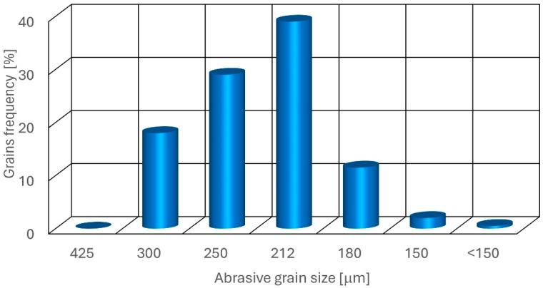
This GSD is engineered to ensure optimal cutting performance in waterjet systems. The uniformity and consistency of the grain sizes are crucial for maintaining steady abrasive flow and achieving precise cutting edges. The absence of oversized grains prevents clogging in the focusing tubes, and the lack of undersized grains minimizes dust generation, enhancing both cutting efficiency and operator safety.
2.3. Test Rig
All research was carried out on the rig, built on the base of the precise abrasive waterjet machining center, the OMAX 60,120 (OMAX Waterjet, Kent, WA, USA). It offers the accurate, repeatable cutting of almost any material by combining high-speed water jet technology with the rigid bridge-style gantry system and a digital control system.
2.4. Design of Experiment (DoE)
A full factorial design of experiment matrix model with three process factors—pressure, abrasive flow rate (AFR), and traverse speed—was used. Factors were chosen based on previous scientific papers [ref. 55,ref. 56] and other articles [ref. 50,ref. 57,ref. 58].
The twenty-seven tests were carried out, according to the L27 array based on the Design of Experiment (DoE). Three levels of the following three control parameters were chosen as follows:
Abrasive Flow Rate: 250, 350, 450 [g/s],
Pressure: 350, 375, 400 [MPa],
Traverse speed: 100, 200, 300 [mm/min].
The following output parameters were selected:
- Cutting depth,
- Roughness of the cut surface Sq,
- Jet deflection angle.
2.5. Measurements
An Olympus DSX1000 optical microscope (Olympus, Tokyo, Japan), which merges remarkable precision and optical performance with smart measuring tools, was used to assess the roughness and the footprint angle of the cut groove’s lateral surface. The angular accuracy in practice, after calibration, is typically ±0.05–±0.2° for angles in the range 0–90°, depending on lighting conditions and surface properties. The accuracy of linear measurements is
- XY: up to 0.01 μm (subpixel interpolation in PRECiV),
- Z: up to 0.1 μm (in 3D mode with autofocus or scanning).
The outcomes of the two output parameters are displayed in Table 6:
Table 6: Control and output factors.
| No | AFR [g/s] | Pressure[MPa] | Traverse Speed[mm/min] | Depth of Cut[mm] | Roughness Sq[μm] | Deflection Angle λ[°] |
|---|---|---|---|---|---|---|
| 1 | 250 | 350 | 100 | 20.09 | 4.9430 | 8.58 |
| 2 | 250 | 350 | 200 | 10.74 | 7.1000 | 16.65 |
| 3 | 250 | 350 | 300 | 7.86 | 8.9420 | 36.74 |
| 4 | 250 | 375 | 100 | 19.79 | 4.9920 | 6.36 |
| 5 | 250 | 375 | 200 | 11.63 | 7.0100 | 15.67 |
| 6 | 250 | 375 | 300 | 8.64 | 8.0000 | 29.04 |
| 7 | 250 | 400 | 100 | 20.30 | 4.5270 | 8.52 |
| 8 | 250 | 400 | 200 | 12.89 | 6.7050 | 14.59 |
| 9 | 250 | 400 | 300 | 8.90 | 7.8610 | 30.85 |
| 10 | 350 | 350 | 100 | 20.21 | 4.2300 | 4.80 |
| 11 | 350 | 350 | 200 | 12.87 | 5.7000 | 13.63 |
| 12 | 350 | 350 | 300 | 8.37 | 6.9000 | 28.60 |
| 13 | 350 | 375 | 100 | 17.06 | 4.3470 | 7.32 |
| 14 | 350 | 375 | 200 | 12.30 | 5.3390 | 12.10 |
| 15 | 350 | 375 | 300 | 9.08 | 6.3060 | 27.13 |
| 16 | 350 | 400 | 100 | 21.06 | 3.8820 | 6.83 |
| 17 | 350 | 400 | 200 | 13.75 | 5.3710 | 14.68 |
| 18 | 350 | 400 | 300 | 9.78 | 6.7000 | 19.64 |
| 19 | 450 | 350 | 100 | 20.81 | 3.8140 | 6.33 |
| 20 | 450 | 350 | 200 | 12.76 | 5.2350 | 14.31 |
| 21 | 450 | 350 | 300 | 9.08 | 5.4290 | 22.41 |
| 22 | 450 | 375 | 100 | 20.80 | 3.8630 | 3.57 |
| 23 | 450 | 375 | 200 | 12.07 | 5.0649 | 13.07 |
| 24 | 450 | 375 | 300 | 9.96 | 5.1610 | 18.87 |
| 25 | 450 | 400 | 100 | 21.14 | 3.8770 | 5.56 |
| 26 | 450 | 400 | 200 | 14.53 | 4.8950 | 11.12 |
| 27 | 450 | 400 | 300 | 11.05 | 5.4160 | 18.18 |
The Sq parameter was selected to evaluate the cutting quality. Sq provides a statistical measure of surface roughness and highlights the distribution of surface heights. It is useful when recognizing surfaces with different topographical distributions but similar Sa values. Sq is calculated based on the following equation:
where
- A is measuring area,
- x and y are linear dimensions of an area.
The Sq factor is most useful for complex surface texture and is therefore preferred in high-precision fields where surface interactions are essential. Sq is more appropriate for applications where surface texture details are significant and could impact performance. Additionally, it is useful for assessing surfaces subject to specific interactions, e.g., with fluids or intense tribological effects.
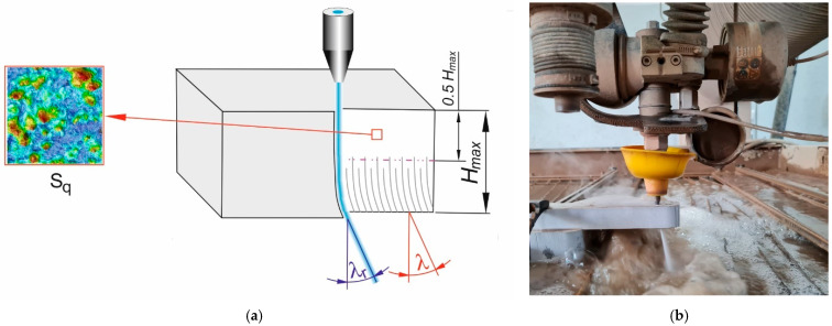
The Sq surface roughness (root mean square height) coefficient is often specified at the lowest value. Half the practical depth of cut, or roughly half the maximum depth of cut Hmax, was chosen as the site for the roughness measurement region (Figure 2). The workspace measured 0.977 mm by 0.977 mm. The measurement signals were processed using a Gaussian band-pass filter in accordance with ISO 25178-3 [ref. 59] to separate macro-geometry (form, waviness) from intrinsic roughness. The following measurement parameters were adopted for the tests:
S-Filter: λs = 2.5 µm
L-Filter: λc = 0.08 mm (cut-off)
The λ footprint angle characterizes cut efficiency and quality, requiring a minimal value. To eliminate the potential errors across the whole sample, footprint angles were measured five times for different footprints on each surface, and then the average value was considered.
3. Results and Discussion
Control parameters, their values, and output values are listed in Table 6.
3.1. Cutting Depth
Cutting depth is one of the criteria for evaluating the efficiency of AWJ machining, commonly used in many scientific and research centers [ref. 60,ref. 61]. The maximum cutting depth was used in this research due to the unambiguous evaluation. Based on test results (Table 5), the polynomial model of process control parameters’ influence on cutting depth was created:
Hx1x2x3x1x2x3x12x22x32x1·x2x1·x3x2·x3
where
- H is cutting depth [mm],
- x1 is abrasive flow rate [g/min],
- x2 is pressure [MPa],
- x3 is the traverse speed [mm/min].
An example graphical illustration of this equation is presented in Figure 3.
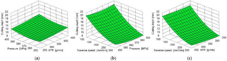
The strong dependence of cutting depth on traverse speed is evident, as the lowest feed rate achieved relatively high cutting depth under all other conditions.
The pressure has a second-order effect. High-pressure increases result in a decrease in the cutting depth in the tested area, most noticeable at the highest traverse speed.
Among the tested control parameters, the abrasive mass flow rate (AFR) per cut depth achieved the lowest result. Noteworthy is the relatively small relationship between cut depth and AFR for the lowest feed rates tested.
Table 7 shows the analysis of variance of the cutting depth.
Table 7: Analysis of Variance of Cutting Depth.
| Source | DF | Adj SS | Adj MS | F-Value | p-Value |
|---|---|---|---|---|---|
| Model | 9 | 582.965 | 64.774 | 97.22 | 0.000 |
| Linear | 3 | 552.875 | 184.292 | 276.62 | 0.000 |
| ma | 1 | 7.169 | 7.169 | 10.76 | 0.004 |
| p | 1 | 6.254 | 6.254 | 9.39 | 0.007 |
| vp | 1 | 539.452 | 539.452 | 809.70 | 0.000 |
| Square | 3 | 28.913 | 9.638 | 14.47 | 0.000 |
| ma*ma | 1 | 0.308 | 0.308 | 0.46 | 0.506 |
| p*p | 1 | 3.390 | 3.390 | 5.09 | 0.038 |
| vp*vp | 1 | 25.215 | 25.215 | 37.85 | 0.000 |
| 2-Way Interaction | 3 | 1.177 | 0.392 | 0.59 | 0.631 |
| ma*p | 1 | 0.037 | 0.037 | 0.06 | 0.816 |
| ma*vp | 1 | 0.375 | 0.375 | 0.56 | 0.464 |
| p*vp | 1 | 0.765 | 0.765 | 1.15 | 0.299 |
| Error | 17 | 11.326 | 0.666 | ||
| Total | 26 | 594.291 | |||
| Model summary: | R298.09% | R2(adj)97.09% | R2(pred)95.99% | ||
DF—Degrees of Freedom, SS—Sum of Squares, MS—Mean Square.
3.2. Surface Roughness
A cut surface roughness is one of the criteria for assessing the quality of AWJ machining [ref. 62,ref. 63]. The roughness measure Sq was utilized in the research, which is, in fact, the root mean square value of the ordinate values in the defining area. It is comparable to the height standard deviation and recommended for determining the surface after AWJ cutting [ref. 64,ref. 65].
Based on research, the polynomial model of process control parameters’ influence on surface roughness was created:
Sx1x2x3x1x2x3x12x22x32x1·x2x1·x3x2x3x3
where
- S is the surface roughness factor Sq [μm],
- x1 is abrasive flow rate [g/min],
- x2 is pressure [MPa],
- x3 is the traverse speed [mm/min].
This equation is graphically illustrated in Figure 4.
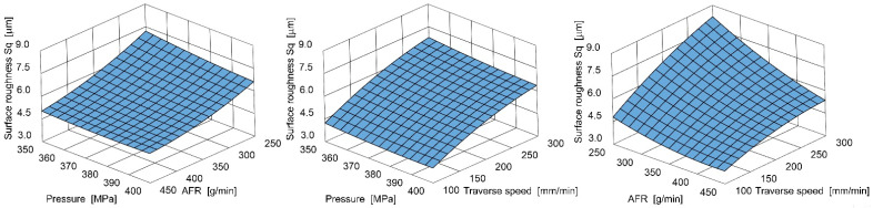
Additionally, in this case, the strong dependency of cut surface roughness on the traverse speed is evident. However, the abrasive flow rate (AFR) has a secondary influence here, while pressure has the least influence among the tested control parameters.
Table 8 shows the analysis of variance of the Sq cutting surface roughness.
Table 8: Analysis of variance of the Sq cutting surface roughness.
| Source | DF | Adj SS | Adj MS | F-Value | p-Value |
|---|---|---|---|---|---|
| Model | 9 | 48.9500 | 5.4389 | 119.74 | 0.000 |
| Linear | 3 | 44.6741 | 14.8914 | 327.84 | 0.000 |
| ma | 1 | 16.6755 | 16.6755 | 367.12 | 0.000 |
| p | 1 | 0.5199 | 0.5199 | 11.44 | 0.004 |
| vp | 1 | 27.4788 | 27.4788 | 604.96 | 0.000 |
| Square | 3 | 1.1427 | 0.3809 | 8.39 | 0.001 |
| ma*ma | 1 | 0.5172 | 0.5172 | 11.39 | 0.004 |
| p*p | 1 | 0.0343 | 0.0343 | 0.76 | 0.397 |
| vp*vp | 1 | 0.5911 | 0.5911 | 13.01 | 0.002 |
| 2-Way Interaction | 3 | 3.1332 | 1.0444 | 22.99 | 0.000 |
| ma*p | 1 | 0.2139 | 0.2139 | 4.71 | 0.044 |
| ma*vp | 1 | 2.8900 | 2.8900 | 63.63 | 0.000 |
| p*vp | 1 | 0.0293 | 0.0293 | 0.65 | 0.433 |
| Error | 17 | 0.7722 | 0.0454 | ||
| Total | 26 | 49.7222 | |||
| Model summary: | R298.45% | R2(adj)97.62% | R2(pred)96.13% | ||
DF—Degrees of Freedom, SS—Sum of Squares, MS—Mean Square.
3.3. Footprint Angle
AWJ effects were reflected on the machined surface in the curvilinear machining footprint forms and were measured to determine the jet deflection angle, as shown in Figure 2.
Based on research, the polynomial model of process control parameters’ influence on the deflection angle was created:
D(x1x2x3x1x2x3x12x22x32x1·x2x1·x3x2x3
where
- D is the deflection angle [deg],
- x1 is abrasive flow rate [g/min],
- x2 is pressure [MPa],
- x3 is the traverse speed [mm/min].
An example illustration of this equation is shown in Figure 5.
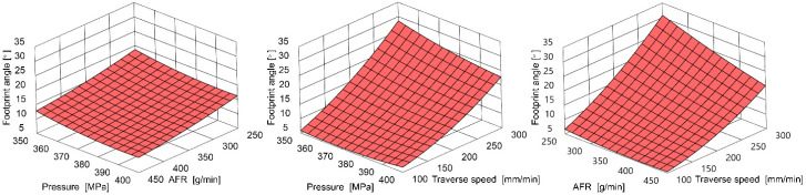
The strong deviation angle dependence on the feed rate is visible. However, the abrasive flow rate (AFR) and pressure have a secondary order of influence among the tested control parameters.
Table 9 shows analysis of variance of the λ footprint angle.
Table 9: Analysis of variance of the λ footprint angle.
| Source | DF | Adj SS | Adj MS | F-Value | p-Value |
|---|---|---|---|---|---|
| Model | 9 | 1998.97 | 222.11 | 56.06 | 0.000 |
| Linear | 3 | 1860.66 | 620.22 | 156.55 | 0.000 |
| ma | 1 | 159.49 | 159.49 | 40.26 | 0.000 |
| p | 1 | 27.08 | 27.08 | 6.84 | 0.018 |
| vp | 1 | 1674.08 | 1674.08 | 422.57 | 0.000 |
| Square | 3 | 33.13 | 11.04 | 2.79 | 0.072 |
| ma*ma | 1 | 2.22 | 2.22 | 0.56 | 0.464 |
| p*p | 1 | 4.60 | 4.60 | 1.16 | 0.296 |
| vp*vp | 1 | 26.31 | 26.31 | 6.64 | 0.020 |
| 2-Way Interaction | 3 | 105.18 | 35.06 | 8.85 | 0.001 |
| ma*p | 1 | 0.00 | 0.00 | 0.00 | 0.979 |
| ma*vp | 1 | 70.91 | 70.91 | 17.90 | 0.001 |
| p*vp | 1 | 34.27 | 34.27 | 8.65 | 0.009 |
| Error | 17 | 67.35 | 3.96 | ||
| Total | 26 | 2066.32 | |||
| Model summary: | R296.74% | R2(adj)95.02% | R2(pred)91.59% | ||
DF—Degrees of Freedom, SS—Sum of Squares, MS—Mean Square.
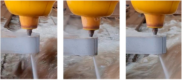
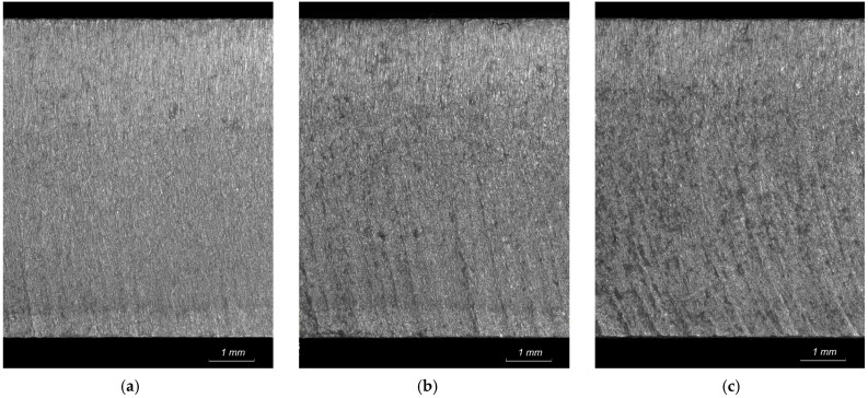
Figure 6 shows examples of various l-angles throughout the cutting process. Figure 7 illustrates their relation to the machining footprints on the surface cut. The λ angle increases as the feed rate increases, and the larger curvature of the machining imprints confirms these observations.
3.4. Image Analysis to Support the AWJ Parameters Optimization
The parameters of the AWJ process, such as the pressure, cutting speed, nozzle stand-off distance, etc., are monitored separately by the process controller. In typical situations, the required cutting precision is achieved by tuning experimental process parameters. This leads to potential processing precision inaccuracy, as the real process is performed in environmental conditions and process-specified parameter uncertainty and instability.
The physical parameters of the process are expected to vary over time, and the control process usually assumes that the variations are of such a magnitude that they can be accepted within the tolerance of processing accuracy. The human-based control parameter selections are usually completed when an acceptable result is obtained under time-specific conditions.
Image analysis techniques are one of the controlling concepts of AWJ processing quality and overall performance. Some examples of image analysis applications are described in the literature, including
- support in the process of removal of organic coatings with rotating water jets, and the image analysis was applied to identify exposed steel areas [ref. 66],
- identification of cutting regions by detecting glass materials in AWJ-based CNC processes [ref. 67],
- identification of geometrical features of holes trepanned with AWJ [ref. 68] to assess the processing precision,
- identification of AWJ processing burr areas that require additional finishing [ref. 69],
- observation of cutting front parameters with thermal or optical cameras [ref. 48].
In general, the AWJ process can be supported by an image analysis system to improve operation accuracy, energy and material usage optimization, process time effectiveness, or other factors. The most desired effect of the operation of such a system should be the multicriteria system processing time improvement, cost, energy, and material effectiveness.
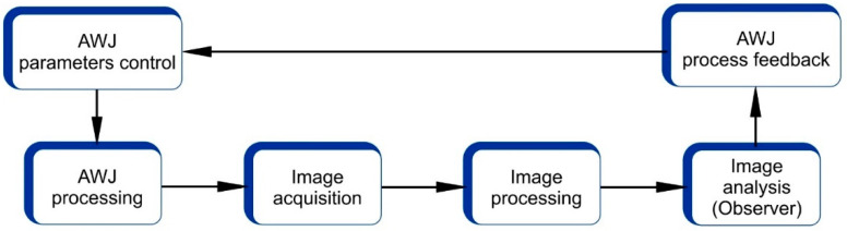
The structure of such a system would comprise an image acquisition module, an image processing module, a parameter observer module, and a process feedback module (Figure 8).
4. Conclusions
Grounded on the research, mathematical models of the machining process were established, showing the cutting depth, surface roughness, and jet deflection angle. For this purpose, second-degree polynomial equations were used, with three variables representing the control parameters of the AWJ cutting process.
The ability to evaluate the jet deflection angle was determined. This demonstrated the potential for correcting actual machining conditions to achieve the required throughput while maintaining the intended surface quality.
Measuring the deflection angle during the cutting process confirmed its control possibility, enabling steering of process efficiency while maintaining the intended cut surface quality.
Deflection angle measurement is another relatively simple alternative to the cutting process status control and to monitoring its quality and efficiency.
Further research will examine the technical feasibility of measuring the jet deflection angle using real-time digital optical analysis systems.
This will involve studying image acquisition during cutting, followed by image processing and analysis.
The precise relationship between the jet deflection angle and the condition of the cut surface will be investigated.
In the practical aspect of the cutting process, observing the jet deflection angle will allow the determination of process stability, especially when cutting natural materials characterized by property variability, such as rock materials.
References
- A. Perec. Multiple Response Optimization of Abrasive Water Jet Cutting Process Using Response Surface Methodology (RSM). Procedia Comput. Sci., 2021. [DOI]
- D. Lehocka, F. Botko, J. Klich, L. Sitek, P. Hvizdos, M. Fides, R. Cep. Effect of Pulsating Water Jet Disintegration on Hardness and Elasticity Modulus of Austenitic Stainless Steel AISI 304L. Int. J. Adv. Manuf. Technol., 2020. [DOI]
- J. Poloprudský, A. Nag, T. Kruml, S. Hloch. Effects of Liquid Droplet Volume and Impact Frequency on the Integrity of Al Alloy AW2014 Exposed to Subsonic Speeds of Pulsating Water Jets. Wear, 2022. [DOI]
- A. Perec, E. Kawecka, F. Pude. Enhancing High-Alloy Steel Cutting with Abrasive Water Injection Jet (AWIJ) Technology: An Approach Using the Response Surface Methodology (RSM). Materials, 2024. [DOI | PubMed]
- A. Perec, A. Radomska-Zalas, A. Fajdek-Bieda, E. Kawecka. Efficiency of Tool Steel Cutting by Water Jet with Recycled Abrasive Materials. Materials, 2022. [DOI | PubMed]
- A. Radomska-Zalas. Experimental Research on the Use of a Selected Multi-Criteria Method for the Cutting of Titanium Alloy with an Abrasive Water Jet. Materials, 2023. [DOI | PubMed]
- G. Peng, T. Itou, Y. Oguma, S. Shimizu. Effect of Ventilation on the Velocity Decay of Cavitating Submerged Water Jet. Fluid-Structure-Sound Interactions and Control, 2019
- S. Shimizu, M. Sakuma, K. Hitomi, K. Akiyama, G. Peng. Submerged Cutting by Abrasive Suspension Jets. Trans. Jpn. Soc. Mech. Eng. Ser. B, 2011. [DOI]
- D. Doreswamy. Machining of D2 Heat Treated Steel Using Abrasive Water Jet: The Effect of Standoff Distance and Feed Rate on Kerf Width and Surface Roughness. Int. J. Res. Eng. Technol., 2014. [DOI]
- L. Dekster, N.E. Karkalos, R. Kudelski, P. Karmiris-Obratański. Experimental Study on Multipass AWJ Performance on Hardox 500 Workpieces. Acta Tech. Napoc.-Ser. Appl. Math. Mech. Eng., 2023
- S. Hloch, P. Hlaváček, K. Vasilko, J. Cárach, I. Samardžić, D. Kozak, I. Hlavatý, J. Scucka, J. Klich, D. Klichova. Abrasive Waterjet (AWJ) Titanium Tangential Turning Evaluation. Metalurgija, 2014
- L. Hlaváč, L. Gembalová, P. Stěpán, I. Hlaváčová. Improvement of Abrasive Water Jet Machining Accuracy for Titanium and TiNb Alloy. Int. J. Adv. Manuf. Technol., 2015. [DOI]
- L. Dekster. Influence of AWJ Parameters on Surface Quality and Material Removal in WNiFe Tungsten Alloy. Adv. Sci. Technol. Res. J., 2024. [DOI]
- T. Szatkiewicz, D. Laskowska, B. Bałasz, K. Mitura. The Influence of the Structure Parameters on the Mechanical Properties of Cylindrically Mapped Gyroid TPMS Fabricated by Selective Laser Melting with 316L Stainless Steel Powder. Materials, 2022. [DOI | PubMed]
- A. Nag, J. Scucka, P. Hlavacek, D. Klichova, A.K. Srivastava, S. Hloch, A.R. Dixit, J. Foldyna, M. Zelenak. Hybrid Aluminium Matrix Composite AWJ Turning Using Olivine and Barton Garnet. Int. J. Adv. Manuf. Technol., 2018. [DOI]
- M. Santhanakumar, R. Adalarasan, M. Rajmohan. Experimental Modelling and Analysis in Abrasive Waterjet Cutting of Ceramic Tiles Using Grey-Based Response Surface Methodology. Arab. J. Sci. Eng., 2015. [DOI]
- M. Hashish. Abrasive Waterjet Machining. Materials, 2024. [DOI | PubMed]
- A.W. Momber, R. Kovacevic. Principles of Abrasive Water Jet Machining, 2012
- I. Finnie. Erosion of Surfaces by Solid Particles. Wear, 1960. [DOI]
- J.G.A. Bitter. A Study of Erosion Phenomena Part I. Wear, 1963. [DOI]
- M. Hashish. A Model for Abrasive-Waterjet (AWJ) Machining. J. Eng. Mater. Technol., 1989. [DOI]
- J. Folkes. Waterjet—An Innovative Tool for Manufacturing. J. Mater. Process. Technol., 2009. [DOI]
- D.A. Axinte, D.S. Srinivasu, J. Billingham, M. Cooper. Geometrical Modelling of Abrasive Waterjet Footprints: A Study for 90° Jet Impact Angle. CIRP Ann., 2010. [DOI]
- P.H.-T. Liu, E. Schubert. Micro Abrasive-Waterjet Technology. Versatility of Waterjet Technology, 2024
- A.M. Hoogstrate, B. Karpuschewski, C.A. Van Luttervelt, H.J.J. Kals. Modelling of High Velocity, Loose Abrasive Machining Processes. CIRP Ann., 2002. [DOI]
- M. Kantha Babu, O.V. Krishnaiah Chetty. A Study on Recycling of Abrasives in Abrasive Water Jet Machining. Wear, 2003. [DOI]
- A. Perec, E. Kawecka, A. Radomska-Zalas, F. Pude. Optimization of Abrasive Waterjet Cutting by Using the CODAS Method with Regard to Interdependent Processing Parameters. Stroj. Vestn.–J. Mech. Eng., 2023. [DOI]
- P. Jandačka, J. Ščučka, P. Martinec, M. Lupták, I. Janeček, S.M. Mahdi Niktabar, M. Zeleňák, P. Hlaváček. Optimal Abrasive Mass Flow Rate for Rock Erosion in AWJ Machining. Advances in Water Jetting, 2021
- Standard Contact Free Cutting. Water Jet Cutting. Geometrical Product Specification and Quality, 2010
- Jagadish, K. Gupta. Abrasive Water Jet Machining of Engineering Materials, 2020
- B. Ganovska, M. Molitoris, A. Hosovsky, J. Pitel, J. Krolczyk, A. Ruggierio, G. Krolczyk, S. Hloch. Design of the Model for the On-Line Control of the AWJ Technology Based on Neural Networks. Indian J. Eng. Mater. Sci., 2016
- R. Rozanski, E. Kawecka, A. Perec. Classification of the Cutting Surface Topography Using a Set of Uncorrelated Parameters with High Discriminative Ability. Materials, 2025. [DOI | PubMed]
- A. Perec, A. Radomska-Zalas, A. Fajdek-Bieda, F. Pude. Process Optimization by Applying the Response Surface Methodology (RSM) to the Abrasive Suspension Water Jet Cutting of Phenolic Composites. Facta Univ. Ser. Mech. Eng., 2023. [DOI]
- J. Praźmo, E. Kawecka, M. Forysiewicz, A. Radomska-Zalas, A. Perec. Influence of Abrasive Water Jet Cutting Parameters on the Surface Properties of Modern Plain Bearing Materials. Advances in Water Jetting II, 2025
- E. Kawecka. The Whale Optimization Algorithm in Abrasive Water Jet Machining of Tool Steel. Procedia Comput. Sci., 2023. [DOI]
- A. Perec, W. Musial. Multiple Criteria Optimization of Abrasive Water Jet Cutting Using Entropy-VIKOR Approach. Advances in Manufacturing Engineering and Materials II, 2021
- A. Perec, E. Kawecka, A. Radomska-Zalas, F. Pude, G. Galecki. Multiple-Criteria Optimization of the Water Jet Cutting Process Using WISP Methodology. Advances in Water Jetting II, 2025
- I.A. Popan, V.I. Bocăneț, S. Softic, A.I. Popan, N. Panc, N. Balc. Artificial Intelligence Model Used for Optimizing Abrasive Water Jet Machining Parameters to Minimize Delamination in Carbon Fiber-Reinforced Polymer. Appl. Sci., 2024. [DOI]
- A. Perec, E. Kawecka. Modeling of the Abrasive Water Jet Machining by ANN in Uncertainty Conditions. Procedia Comput. Sci., 2024. [DOI]
- M. Ficko, D. Begic-Hajdarevic, M. Cohodar Husic, L. Berus, A. Cekic, S. Klancnik. Prediction of Surface Roughness of an Abrasive Water Jet Cut Using an Artificial Neural Network. Materials, 2021. [DOI | PubMed]
- M. Szada-Borzyszkowska, W. Kacalak, K. Banaszek, F. Pude, A. Perec, K. Wegener, G. Królczyk. Assessment of the Effectiveness of High-Pressure Water Jet Machining Generated Using Self-Excited Pulsating Heads. Int. J. Adv. Manuf. Technol., 2024. [DOI]
- L. Dahil, İ. Dahil, A. Karabulut. Comparison of Advanced Cutting Techniques on Hardox 500 Steel Material and the Effect of Structural Properties of the Material. Metalurgija, 2014
- T. Krenicky, M. Servatka, S. Gaspar, J. Mascenik. Abrasive Water Jet Cutting of Hardox Steels—Quality Investigation. Processes, 2020. [DOI]
- J. Poloprudský, A. Chlupová, I. Šulák, T. Kruml, S. Hloch. Surface and Subsurface Analysis of Stainless Steel and Titanium Alloys Exposed to Ultrasonic Pulsating Water Jet. Materials, 2021. [DOI | PubMed]
- Y. Yuan, J. Chen, H. Gao. Surface Profile Evolution Model for Titanium Alloy Machined Using Abrasive Waterjet. Int. J. Mech. Sci., 2023. [DOI]
- T. Wala, K. Lis. The Experimental Method of Determining the Forces Operating During the Abrasive Waterjet Cutting Process—A Mathematical Model of the Jet Deviation Angle. Industrial Measurements in Machining, 2020
- M. Brandstätter, A. Wöhrle, M. Kaufeld, F. Pude, A. Nag, S. Hloch. The Quantitative Evaluation of the Cutting Surface Quality Levels in Abrasive Water Jet Cutting by Measurement of the Representative Striation Mark Displacement. Int. J. Adv. Manuf. Technol., 2022. [DOI]
- A. Lebar, M. Jerman, I. Sabotin, P. Drešar, J. Valentinčič. AWJ Cutting Process Control by Means of Process Visualisation. Procedia Eng., 2016. [DOI]
- D. Arola, M. Ramulu. Mechanisms of Material Removal in Abrasive Waterjet Machining of Common Aerospace Materials. Proceedings of the 7th American Water Jet Conference 1993, 1993
- P. Hlaváček, J. Cárach, S. Hloch, K. Vasilko, D. Klichová, J. Klich, D. Lehocká. Sandstone Turning by Abrasive Waterjet. Rock Mech. Rock Eng., 2015. [DOI]
- P. Martinec, J. Vašek, J. Foldyna, L. Sitek. Abrasives for AWJ Cutting, 2002
- GMA Garnet Group Our Garnet for Future Generations
- J. Prazmo, R. Sobczak, A. Perec. Abrasive Grain Disintegration during High-Pressure Abrasive Water Jet Cutting in the Abrasive Reuse Aspect. Proceedings of the Conference on Water Jetting Technology: Water Jet 2017—Research, Development, Application, 2017
- China Garnet J80A 50-80mesh
- E. Kawecka. The Use of Metaheuristic Optimization Algorithm in Abrasive Water Jet Machining of White Marble. Proceedings of the XIV International Conference Electromachining 2023, 2024. [DOI]
- A. Perec, E. Kawecka, J. Podhajecki, A. Radomska-Zalas, M. Krakowiak, A. Nag. Comparison of Chosen Metaheuristic Algorithms for the Optimization of the Abrasive Water Jet Treatment Process. MM Sci. J., 2024. [DOI]
- S. Spadło, D. Krajcarz. Study of the Geometrical Structure of Copper Surface after Abrasive Waterjet Cutting. IOP Conf. Ser. Mater. Sci. Eng., 2018. [DOI]
- A. Radomska-Zalas. Multi-Criteria Methods in the Optimization of the Abrasive Waterjet Cutting Process. AIP Conf. Proc., 2024. [DOI]
- 59.ISO 25178-3Geometrical Product Specifications (GPS)—Surface Texture: Areal. Part 3: Specification OperatorsISOGeneva, Switzerland2012
- M. Jerman, J. Valentinčič, A. Lebar, H. Orbanić. The Study of Abrasive Water Jet Cutting Front Development Using a Two-Dimensional Cellular Automata Model. Stroj. Vestn.–J. Mech. Eng., 2015. [DOI]
- G. Chomka, M. Kasperowicz, J. Chodór, J. Chudy, L. Kukiełka. Possibilities of Rock Processing with a High-Pressure Abrasive Waterjet with an Aspect Terms to Minimizing Energy Consumption. Materials, 2023. [DOI | PubMed]
- D. Klichova, A. Nag, J. Poloprudský, J. Foldyna, F. Pude, L. Sitek, S. Hloch. Utilising of Water Hammer Effect for Surface Roughening of Ti6Al4V. Int. J. Adv. Manuf. Technol., 2023. [DOI]
- J. Carach, D. Lehocka, S. Legutko, S. Hloch, S. Chattopadhyaya, A.R. Dixit. Surface Roughness of Graphite and Aluminium Alloy After Hydro-Abrasive Machining. Advances in Manufacturing (Manufacturing 2017), 2018
- N. Yuvaraj, M.P. Kumar. Surface Integrity Studies on Abrasive Water Jet Cutting of AISI D2 Steel. Mater. Manuf. Process., 2017. [DOI]
- M. Leleń, A. Ruggiero, J. Józwik. Geometric Features of a Multilayer Surface After Water Jet Cutting in Variable Cutting Conditions. Manuf. Technol., 2023. [DOI]
- A.W. Momber. Image Processing as a Tool for High-Pressure Water Jet Coating Removal Assessment. Int. J. Adv. Manuf. Technol., 2016. [DOI]
- M.M.D.S. Filho, J.D.N.M. Cabral, C.A.D.S. Filho. Detection of Glass’ Position Using Computer Vision for the Automation of the Waterjet Cutting Machines. Proceedings of the 2022 IEEE International Conference on Automation/XXV Congress of the Chilean Association of Automatic Control (ICA-ACCA)
- C. Datta, R.R. Ravi, D.S. Srinivasu. Vision-Based in-Situ Process Monitoring for Increased Productivity in Abrasive Waterjet Trepanning. Procedia Comput. Sci., 2025. [DOI]
- R.R. Ravi, C. Datta, D.S. Srinivasu. Machine Vision Based Burr Length Measurement in Abrasive Waterjet Trepanning. Manuf. Lett., 2023. [DOI]